
Learning how to make an inverter at home isn’t just a fun electronics project it actually comes in handy when you need backup power during outages, or if you want to set up a simple off-grid solar system. A DIY inverter lets you convert DC power from a battery into AC electricity, which is exactly what a bunch of household devices, lights – fans, maybe even a small appliance or two – need.
If you’re tired of frequent power outages or looking for a cost-effective way to power your RV, home, or off-grid cabin, learning how to make a DIY inverter at home could be the perfect solution.
In this complete guide, I’ll walk you through step-by-step instructions to create your own inverter — whether you want a pure sine wave inverter, a 2000-watt inverter, or simply a 12-volt inverter to run your basic appliances.
And don’t worry — even if you’re a beginner, by the end of this Top Solar Picks Guide, you’ll know exactly how to build an inverter at home, including what tools and parts you need, safety tips, and advanced options like how to make a homemade inverter circuit for welding!
If you’re planning a full off-grid setup, this inverter project works best when combined with a complete solar system design. Understanding how solar energy is used in real homes can help you avoid costly mistakes when building your own system. Solar System for Off-Grid Living: The Complete 2026 Guide
Table of Contents
- What Is an Inverter and How It Works
- Why Build a DIY Inverter at Home
- Tools and Components Needed for a DIY Inverter
- How to Make an Inverter at Home (Step-by-Step Guide)
- Simple DIY Inverter Circuit Diagram Explained
- How Oscillator, Transformer and Transistors Work in an Inverter
- How to Build a 12V Inverter for Home and Solar Use
- Common Mistakes When Building a DIY Inverter
- DIY Inverter Cost vs Buying a Ready-Made Inverter
- Simple Inverter Circuit for Beginners (Explained)
- Frequently Asked Questions About DIY Inverters
- Final Thoughts
This guide on how to make an inverter was last updated by John Tanko on April 20, 2026, to ensure accurate and up-to-date information for homeowners, farmers, and off-grid users.
Quick Overview: DIY Inverter Specifications
| Feature | Typical DIY Inverter |
|---|---|
| Input Voltage | 12V DC Battery |
| Output Voltage | 110V or 220V AC |
| Output Waveform | Square Wave or Pure Sine Wave |
| Power Capacity | 300W – 2000W |
| Main Components | Transformer, MOSFETs, Oscillator IC |
| Common Uses | Backup power, RVs, solar systems |
Related Article:
How to Make a DIY Power Inverter from Scratch (Step-by-Step with Circuit Diagram)
Disclaimer:
This article is intended for educational and informational purposes only. High voltage electricity and complex electronics can be dangerous, potentially deadly, if not worked with properly.
This guide should only be used by someone with experience and knowledge of electrical safety. Do not attempt to construct an inverter when guidance from professionals is not available, if you are not sufficiently qualified.
No liability is accepted by the author or this site for any injuries, damage or loss that may arise from following the guide set out in this article. Make sure to comply with the local electrical codes and safety regulations and use suitable safety equipment when building any electrical project.
Proceed at your own risk.
What Is an Inverter and Why Should You Make One?
Before we dive into the fun part (building!), let’s first understand what an inverter is.
An inverter is an electronic device that converts DC (Direct Current) power from sources like batteries or solar panels into AC (Alternating Current) power that you can use to run home appliances such as lights, fans, refrigerators, and more.
Why Build a DIY Inverter?
- Save money by avoiding expensive off-the-shelf inverters.
- Customize output to suit your unique needs (RV, home, camping, solar).
- Learn valuable electronics and DIY skills.
- Integrate with solar panels for a complete off-grid solar system.
Before building a DIY inverter, it’s important to understand how commercial systems compare in cost and efficiency, especially for home use. Best Solar Inverters for Home Use (2026 Guide): Hybrid, Off-Grid & Budget Picks
Parts and Tools You Need to Build a DIY Inverter at Home
Wondering how to make a simple inverter at home? Here’s a shopping list to get started:
Essential Components:
| Component | Purpose |
|---|---|
| Transformer (12V to 220V/110V) | Steps up DC to usable AC voltage |
| Transistors (e.g., 2N3055, IRFZ44N) | Switch current on/off rapidly |
| Oscillator IC (4047 or 555 Timer) | Generates alternating signal to drive transistors |
| Capacitors & Resistors | Smooth out signals and stabilize the circuit |
| Heat Sink | Prevents overheating of transistors/MOSFETs |
| 12V Battery (Lead-acid or Lithium) | DC power source |
| Wires, Connectors, PCB Board | Assembly and wiring |

Why You Can Trust Top Solar Picks
We compare real-world solar performance, charging reliability, long-term user experiences, and practical testing — not just manufacturer claims. Products from brands like EcoFlow, Bluetti, Jackery, and Eco-Worthy are cross-checked using actual usage data and customer feedback.
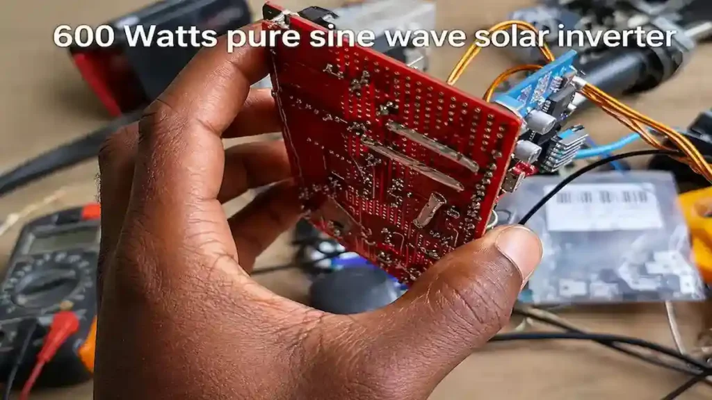
Learn more →PURE SINE WAVE INVERTER PARTS REQUIRED:
- EGS002 SPWM Inverter Driver Module
- IRF3205 or IRLB4132 MOSFETS (16x)
- 12V to 220V (500W/1000W) Transformer
- TO-220 Isolation Set (16x)
- TIP31C NPN Transistor
- 7805 Regulator
- 1N4007 Diode (8x)
- 10k Ohm NTC Thermistor
- 10k Ohm Multi-turn Trimmer
- 10 Ohm Resistor (4x)
- 2.2k Ohm Resistor
- 10k Ohm Resistor (4x)
- 100k Ohm Resistor (2x)
- 470nF 25v Capacitor
- 2.2uF +350v Capacitor
- 2.2uF 25v Capacitor
- 10uF 25v Capacitor
- 100uF 25v Capacitor
How to Make an Inverter at Home (Step-by-Step)
So, let’s break it down. Building a simple inverter isn’t rocket science, especially if you want to turn a 12V battery into AC power for small gadgets. People often use DIY inverters for RVs, backup power, or even solar setups that don’t tie into the grid.
To keep things straightforward, a basic inverter circuit has three main parts: the oscillator circuit, the switching components (like transistors or MOSFETs), and the transformer that bumps up your voltage.
Step 1: Design the Oscillator Circuit
Your first job is to get the oscillator going. This little piece handles the switching signals—basically telling the rest of the circuit when to flip on and off. ICs like the 4047 or a classic 555 timer kick out solid, stable square waves, which is exactly what you want.
Those pulses are what control the switching action and help turn straight DC current into something that looks and acts a lot like AC power.
Step 2: Connect the Switching Transistors or MOSFETs
Next, run the output from your oscillator into a few sturdy power transistors or MOSFETs—something like the IRFZ44N, IRF3205, or even a 2N3055 does the trick. These guys are the high-speed switches that shuttle current back and forth through the transformer.
That back-and-forth is where you get your alternating pattern, the start of your AC output.
Step 3: Install a Step-Up Transformer
Now you need to take that low battery voltage and crank it up to a usable number. Enter the transformer.
Here’s the basic idea:
- Input: 12V DC battery
- Transformer: 12-0-12 center-tapped
- Output: 110V or 220V AC
Through electromagnetic induction, your transformer grabs the low-voltage input and spits out a much higher one, all thanks to magic (and some very neat physics).
Step 4: Connect the 12V Battery Power Source
Wire up the circuit to your 12V battery. This is your main power source. Make sure those wires are beefy enough to handle the current, and double-check all your connections. Things get hot quick if you cut corners here.
Step 5: Test the Inverter With a Small Load
Before plugging in anything valuable, start with something tiny—a 10-watt light bulb or maybe a small desk fan. If it lights up or spins, you’ll know you’re on the right track and your handiwork won’t blow fuses or fry delicate parts.
You’ll find simple inverters are great for keeping the lights on, charging your phone, or powering a fan when you’re off the grid or during blackouts.
Simple DIY Inverter Circuit Diagram Explained
Circuit diagrams sometimes look wild, but really, you’re following three basic stages:
- Oscillator stage
- Switching stage
- Voltage step-up stage
Each one is there for a reason, and together, they make the magic happen.
How the Oscillator Works
Think of the oscillator as the heart of the inverter, thumping out regular pulses. Something like an IC 4047 puts out two opposite square waves, flipping between them again and again.
Those signals run the switches, forcing current to ping-pong through the transformer. Without this, you’d just have boring DC power.
How the Transformer Steps Voltage
The transformer is where the voltage climbs up. You feed current into the primary coil; electromagnetic induction does its thing, and voltage appears in the secondary coil at a much higher level.
So, a brief summary: 12V in, 110V or 220V out—nice and simple.
How Transistors Switch Current
The switching transistors or MOSFETs—call them what you want—are the bouncers controlling which way the current heads. They follow the beat set by the oscillator, alternating the flow to the transformer windings and forcing a kind of artificial AC into existence.
Do that right, and you’ve got the core of most DIY inverters sorted.
How to Build a 12V Inverter at Home
A 12V inverter’s a popular project because so many batteries out there—car, home, solar—work at 12V. Here’s what you’ll need:
- 12V battery (lead-acid or lithium both work)
- Oscillator IC (4047 or a 555 timer)
- Power MOSFETs or transistors
- 12-0-12 center-tapped transformer
- A handful of capacitors and resistors
- Heat sinks (these are your friends!)
The battery gives you the juice, the oscillator sets up those alternating signals, the switches dance to that beat, and the transformer jacks up the voltage for regular AC appliances.
You can use these homemade setups as:
- Emergency backup power
- Power for RVs or camping
- Small off-grid solar projects
Common Mistakes When Building a DIY Inverter
Let’s talk about the usual hiccups. A little know-how goes a long way.
Using the Wrong Transformer Rating
Don’t skimp here. If your transformer can’t handle the power you want, it’ll get hot and die young. For a 1,000-watt inverter, choose a transformer rated for that much or more.
Overheating MOSFETs or Transistors
Switching parts get hot. If you skip real heat sinks—or mount them badly—you’ll see failures fast. Good airflow, solid mounting, and a dab of thermal paste go a long way.
Poor Heat Sink Installation
Even when heat sinks are used, improper mounting can reduce cooling efficiency. Using thermal paste and secure mounting helps transfer heat away from the components.
Incorrect Wiring Connections
Polarity mistakes or loose wires are a recipe for disaster. Double-check how everything’s hooked up before you flick the switch. Adding fuses and solid insulation doesn’t hurt either—it can save you headaches (or worse).
Is It Cheaper to Build an Inverter Yourself?
Sometimes, but not always. DIY inverters can save money, depending on the parts you buy and the power level you need.
Here’s a rough cut for a 500-watt DIY setup:
- Transformer: $20 to $60
- MOSFETs or transistors: $10 to $40
- Other stuff (capacitors, resistors, etc.): $10 to $30
- Cooling bits and wires: $10 to $30
- All in, you might spend $80 to $150 for something basic.
Commercial inverters, though, usually have more safety features and give you cleaner power:
- 500W: $80 to $200
- 1000W: $150 to $400
- 2000W pure sine wave: $400 to $800 or more
If you love tinkering, want something custom, or just like learning about power electronics, DIY definitely has its rewards. For long-term or heavy-duty needs? Store-bought is usually the safer bet. simple Inverter Circuit Diagram for Beginners
If you’re new to this, focus on four main components:
- DC battery
- Oscillator circuit
- Power switches (transistors or MOSFETs)
- Step-up transformer
The rundown goes like this: battery sends 12V DC, oscillator shapes that into square waves, switches alternate the current, transformer boosts the voltage, and bingo—you get AC.
Most simple homebrew inverters make a square wave, good enough for lights, fans, and basic chargers. If you want to run sensitive stuff (think laptops or TVs), you’ll want more advanced features like PWM and filtering to make a true sine wave. But for basic needs? Simple really does the trick.
What is EGS002 Board
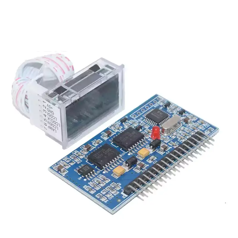
For the construction of Pure Sine Wave inverters, the EGS002 is a flexible $3 all-in-one solution. It can be used to create inverter units from low power to high power. Upon initial delivery, it is not yet an inverter. Building a few parts around it would be necessary to turn it into a working inverter unit.
What Makes It So Excellent?
The cost of good commercial pure sine wave inverters with high power is costly! Their price range is $120-$400. Your choice of input voltage, output voltage, and power ratings allows you to construct a wide variety of inverters with the EGS002! Depending on your specifications and where you get your parts, it might be as cheap as $20.
What’s on the board of the EGS002?
The EG8010 SOIC microcontroller is an ASIC (Application Specific Integrated Circuit) microcontroller chip that is used in the EGS002 to drive H-Bridge inverters by producing SPWM logic signals. The chip also has I/Os that are specifically made for temperature monitoring, fan drive output, closed loop voltage monitoring, and cut-off current monitoring. The chip is preprogrammed and ready to use, in contrast to an Arduino-based inverter project.
Two IR2110S MOSFET drivers are also included on the board to drive an all-N-channel H-bridge MOSFET configuration for SPWM and polarity switching to the transformer or inductor. The low side and high side MOSFETs are specially guaranteed to be fully saturated by this chip.
- By providing the gates with the appropriate gate voltages to guarantee that they have the least amount of on-resistance in accordance with their specifications, this prevents power losses from on-resistance.
OP-AMP for Current Sensing: To increase the voltage from the shunt resistor, the board is equipped with an LM393 OP-AMP. As the chip uses the amplified voltage for overcurrent protection, it returns to the analog input of the EG8010. - LCD Ready Display Output: A proprietary LCD display is already pre-programmed to operate with the EG8010 microprocessor. To obtain the additional LCD screen, you can add one dollar to the $3 EGS002 unit This shows the frequency mode, temperature, output voltage, and current.
- Single LED Error Display: To show errors for troubleshooting, a single red LED on the board would blink for a certain amount of time.
Pure Sine Wave Inverter Circuit
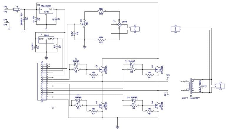
Pro Tip: If you aim for a pure sine wave inverter, you’ll also need PWM controllers, MOSFET drivers (like IR2110), microcontrollers (Arduino), and LC filters.
Step-by-Step: How to Make a DIY Inverter at Home
Ready to get your hands dirty? Follow these easy-to-understand steps.
Step 1: Design the Inverter Circuit (The Brain of Your Inverter)
First, decide on your inverter type:
- Square Wave Inverter (basic, for simple loads like lights and fans).
- Pure Sine Wave Inverter (advanced, for sensitive electronics like laptops).
If you’re starting out, a square wave inverter is easier to build.
Use an oscillator IC (like IC 4047) to create a pulse that will switch the transistors rapidly, mimicking an AC signal.
Step 2: Choose and Prepare Your Transformer
- For 12V input and 220V output, select a 12-0-12 center-tapped transformer.
- For US systems, a 110V output transformer may be required.
- Make sure the transformer can handle your target wattage (e.g., 2000 watt inverter needs a heavy-duty transformer).

Step 3: Building the Switching Circuit (The Muscles)
Connect the oscillator output to transistors/MOSFETs (like IRFZ44N) to drive the transformer.
Important: Use a heat sink and, for high-power setups, cooling fans to prevent components from overheating.
Step 4: Power Up with a 12V Battery
Here’s where “how to make a 12-volt inverter at home” becomes practical:
- Connect the circuit to a 12V DC battery.
- Ensure you use thick gauge wires to handle the current safely.
Step 5: Test Your DIY Inverter!
Connect a small load (like a 10W bulb) to the output.
- If everything is wired correctly, the bulb should light up using AC power generated by your homemade inverter!
Safety Reminder: Never test with high loads first. Always start small to prevent damage and danger.
Upgrading to a Pure Sine Wave Inverter
If you’re thinking “how to make a pure sine wave inverter”, here are additional tips:
- Use Pulse Width Modulation (PWM) to create smoother waveforms.
- Add LC filter circuits to eliminate noise and smooth out voltage.
- Microcontroller (Arduino) can control frequency and waveform accuracy.
- This setup is essential for running laptops, medical equipment, and TVs.
DIY RV Inverter: Portable Off-Grid Power
Many readers wonder how to build an inverter for an RV. Here are must-have features for a DIY RV inverter:
- Compact size but powerful (aim for 1500W to 2000W).
- Solar charge controller compatible for pairing with solar panels.
- Stable output for appliances like fridges, microwaves, and air conditioners.
- 12V system with good battery management.
Pro Tip: Pair your inverter with solar panels for a complete off-grid setup and maximize energy savings!
Special: How to Make a Homemade Inverter Welding Machine
If you’re adventurous and asking “how can I make a homemade inverter welding machine?”, you’ll need:
- High-current MOSFETs/IGBTs.
- Arc ignition circuits.
- Custom heavy-duty transformers.
- Cooling systems (because welding needs high currents).
Caution: DIY welding inverters are advanced projects, requiring expertise in high-voltage electronics!
Cost of Building a DIY Inverter vs. Buying One
| Inverter Type | DIY Cost Estimate | Store-Bought Equivalent |
|---|---|---|
| Square Wave (500W) | $50 – $80 | $150+ |
| Pure Sine Wave (1000W) | $120 – $250 | $400 – $800 |
| RV Inverter (2000W) | $300 – $500 | $700 – $1500 |
| Inverter Welding Machine | $400+ (Advanced skill) | $600 – $2000 |
If you’re planning a full solar setup around your inverter, these guides will also help you size your system correctly. How Many Amps Does a Solar Panel Produce? (100W, 200W, 400W Examples) or MPPT vs PWM: Selecting the Right Solar Charge Controller for Optimal Performance
Related Articles You Should Read Next
- How to Choose The Best Inverter And Battery (Complete 2026 Guide)
- Best Solar Inverters for Home Use (2026 Guide): Hybrid, Off-Grid & Budget Picks
- Off Grid Solar System: How It Works and What You Need to Know
- How many solar panels to charge a 200Ah lithium battery
- Can an Off Grid Solar System Power Your Home 100%? Real Costs and Setup Guide
- Solar Panel Costs in 2026: Price Breakdown & Savings Guide
FAQs: Answering Your Top Questions
How can I make a homemade inverter circuit?
You can make a homemade inverter circuit using IC 4047, transistors like 2N3055, and a center-tapped transformer, paired with a 12V battery.
How to make a simple inverter at home?
Use basic components — oscillator, transformer, transistors — to convert 12V DC to AC for running lights, fans, and small appliances.
How to make a 12-volt inverter at home?
Build a circuit that uses 12V battery input, steps it up via a transformer, and outputs 110V or 220V AC using switching transistors.
Can I build a 2000 watt inverter?
Yes! But you’ll need heavy-duty components: large transformer, high-current MOSFETs, and proper cooling.
What is a pure sine wave inverter?
A pure sine wave inverter produces smooth AC power just like the grid, ideal for sensitive devices like TVs, laptops, and medical equipment.
Last Thoughts
Building your own inverter is a rewarding and money-saving project. Whether you’re powering an RV, setting up a solar system, or preparing for outages, now you know how to build an inverter at home — from a 12-volt inverter to a pure sine wave powerhouse.
Author
John Tanko is the founder of Top Solar Picks and a solar energy researcher whose work has been featured in leading technology and sustainability publications. Learn more on our About page.